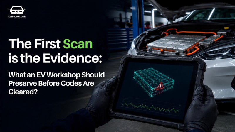
The First Scan Is the Evidence: What an EV Workshop Should Preserve Before Codes Are Cleared

When an EV comes in with a charging fault or a warning light, the diagnostic scan a technician runs in the first few minutes is often the only untouched record of what actually happened — before a reset, low-voltage disconnect, software update, code clear, charging retry or road test overwrites it.
This article, by the iCarsoft team, lays out a tool-independent protocol for EV workshops and technicians: what to record, in what format, and in what order, so that a single code doesn’t get mistaken for a finished diagnosis. It’s especially relevant for India’s service ecosystem, where vehicles move between home AC charging, depot charging and public DC charging under conditions — heat, dust, hurried recovery — that make faults hard to reproduce later.
iCarsoft is an R&D, manufacturing, sales and service of automotive diagnostic equipment, and a government-recognised SRDI (Specialised, Refined, Distinctive, Innovative) enterprise.
Why is a five-character code not a diagnosis?
A Diagnostic Trouble Code (DTC) is a structured observation made by a control unit. SAE J2012 standardises broad code formats, but many definitions, failure-type bytes and test plans remain manufacturer- specific. The same visible symptom may begin in the traction battery, an on-board charger, a coolant circuit, a high-voltage interlock, the 12 V supply, a gateway, the charging station or the electrical installation upstream of it.
The first useful question is therefore not “Which part is bad?” It is “What exactly happened, and what changed between the event and this scan?”
A composite case: one stopped charge, three plausible stories
Consider an illustrative composite case assembled from common charging-complaint patterns.
A vehicle stops an AC charge at 43%. The driver cycles the ignition, reconnects the cable and completes the charge. At the workshop, the warning is absent.
| Finding preserved | What it supports | What it does not prove |
| Charge stopped after 11 minutes at 43% | A time-and-state boundary for reproduction | A traction-battery defect |
| Several modules hold low- voltage/history codes | A shared supply or wake-up hypothesis worth testing | That every listed module failed |
| On-board charger shows no current DTC | No current report in that ECU at scan time | That the charger was fault-free during the event |
| The same vehicle charges on another EVSE | The vehicle/EVSE/site interaction matters | That the vehicle is conclusively fault-free |
With those facts intact, the workshop has three testable paths: an unstable 12 V supply disturbed several controllers; the original EVSE or site supply interrupted the session; or an intermittent vehicle-side condition did not mature into a current code.
None is yet a conclusion. The handoff should say which path the evidence supports and which observation would separate them.
The first-scan protocol
- Preserve the customer’s words before translating them
Record the exact warning text, lamp colour, chime and affected function. Did the vehicle fail to enter Ready, lose propulsion, limit power, stop charging, disable regeneration or only change the range estimate? Note whether the symptom cleared after an ignition cycle and whether it returned.
“Stopped charging at 43%” is evidence; “battery failed” is interpretation.
- Identify the vehicle and the diagnostic session
Save the VIN, model year, powertrain, sales region and available software or calibration identifiers. Record whether vehicle identification was automatic or manually selected, along with the diagnostic application version, interface/VCI and connection method. A report without session identity is difficult to reproduce and easy to misread after software changes.
- Save topology, including silence
A successful connection to one legislated OBD service does not mean every EV control unit was scanned. Save the full topology or health report, where supported: responding modules, non-responding modules, gateway/security status and scan time. Write “not queried” or “no communication”, not “no fault”, when a module was not actually reached.
- Record the low-voltage baseline
Electronic diagnosis depends on a stable low-voltage supply. Record the measured auxiliary-battery voltage, the vehicle state during measurement and whether a regulated support unit was connected. Low supply voltage can explain noise across several modules, but it must remain a hypothesis until checked against vehicle-specific procedures. It should not be used to erase unrelated evidence.
- Preserve each DTC as a tuple, not a screenshot fragment
For each relevant DTC, keep the reporting ECU, full code, subtype or failure-type byte, original text, status (current, pending, history, stored or permanent), occurrence/ageing counters where available, and the source of the definition. A cropped picture of “P0xxx” without the ECU and status is not a complete record.
- Separate event data from live data
Freeze-frame, snapshot or extended records may describe the moment a monitor failed. Live data describes the vehicle now. Label each parameter with its source, unit and time basis. A cell-voltage spread measured after the pack has cooled or after the vehicle has restarted must not be presented as the value at the time of the complaint.
- Draw a line before every state-changing action
Before clearing codes, disconnecting the 12 V supply, resetting adaptations, running active tests, programming, updating software, charging again or road-testing, export the initial report. Then log the action, time, preconditions and result. This creates a before-and-after record instead of mixing original evidence with evidence created by the diagnostic process.
A handoff another technician can use
A useful escalation does not need every available parameter. It needs the smallest record that allows a qualified technician to choose the next vehicle-specific test without repeating the entire intake.
|
Handoff block |
Minimum useful content |
|
Event |
Customer’s exact words; time; mileage; Ready/driving/charging state; AC or DC; EVSE/site if known |
|
Vehicle |
VIN; model year; powertrain/pack variant if available; region; software/calibration identifiers |
|
Session |
Tool/application version; VCI; connection; automatic or manual identification; scan time |
|
Topology |
Responding and non-responding modules; gateway/security status; scan scope |
|
Codes |
Reporting ECU; complete DTC; subtype; original wording; status; counters; definition source |
|
Data |
Freeze-frame/event record separately from current live values; original units; timestamp |
|
Interventions |
Code clear, reset, power cycle, battery support, charging attempt, road test, programming or parts fitted |
|
Boundary |
Last known vehicle state; hazards; work not performed; next authorised test or escalation route |
What this record cannot claim
- A DTC proves that the component named in its description has failed.
- A generic OBD scan is equivalent to a manufacturer-level full-system session.
- No DTC means the high-voltage system is safe or de-energised.
- A current live value is the value that existed when the event occurred.
- A menu item proves that a test, reset or programming function is supported on that exact vehicle.
The most valuable diagnostic habit is not knowing more code definitions. It is resisting the urge to collapse observation, measurement and conclusion into one sentence. A well-built first-scan record keeps those layers separate. It reduces repeated labour, protects evidence during escalation and gives the next technician a defensible place to begin.
Also read: The missing link in EV battery management: Independent Diagnostics
Subscribe & Stay Informed
Subscribe today for free and stay on top of latest developments in EV domain.