Field Oriented Control of Permanent Magnet Synchronous Motor in electric vehicles | Whitepaper by Sterling Gtake

Abstract
This paper details the implementation of Field Oriented Control (FOC) of Permanent Magnet Synchronous Motor (PMSM) using indirect current control method.
Due to a permanent magnet rotor, PMSM motors have very high efficiency, reliability and are fast in response. The PMSM motor finds application in domestic and commercial sectors, especially in Medical, Electric vehicles and Position control systems. The proposed FOC is modelled for a PMSM motor rated at 8kW, 300 volts and 8 Nm torque, and its performance is simulated in MATLAB/SIMULINK environment. The obtained results from the simulation are validated by developing a prototype motor control unit, and the FOC algorithm is implemented in Texas Instruments make TMS320F280041PZS. To check the robustness of the developed FOC algorithm, a wide range of speed and torque transients are considered. Simulation and experimental results indicate that the FOC algorithm performs well in controlling the torque and speed of the PMSM motor with satisfactory results.
1. Introduction
Electric vehicles, also referred to as battery electric vehicles, have an electric motor instead of an internal combustion engine.
High-performance motors need a control mechanism that ensures effectiveness, enhanced smoothness, reliability, and efficiency. One such example is of electric-vehicle (EV), which can be controlled by a field-oriented-control (FOC) based system.
For the present work, a PMSM motor [2] is considered, i.e. brushless motor having permanent magnets on the rotor. The working of the PMSM motor is quite like the BLDC [1] motor. However, the change lies in the waveform due to which back emf is sinusoidal in nature for PMSM; whereas for BLDC, it is trapezoidal in nature. PMSM offers high torque density and high efficiency as compared to that of induction motor. There are two general methods; one is called the direct or feed-back method, and the other is known as the indirect or feed-forward method; these two methods differ in the way the rotor angle is calculated [5].
While implementing FOC [6], transformation of stator currents is required from the stationary reference frame to the rotor flux reference frame, which is known as the d-q reference frame. In FOC control, three-phase time variant stator reference frames are transformed to the two-axis rotating d-q rotor reference frame.
2. Proposed method for FOC
The proposed FOC for PMSM motor is simulated in MATLAB/Simulink environment comprising of current and torque angle calculator, stator current synthesizer, inverter, PMSM motor and signal conditioner. PI controller contains the two-gain parameter, i.e., proportional gain (Kp) and integral gain (Ki). Therefore, for the control of the PMSM drive, Kp and Ki gain proper tunning is of prime concern [10].
2.1 Simulation & Control Scheme for PMSM Drive
The three-phase reference currents [5] in PMSM are defined as:
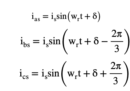
ias, ibs, ics are simulated reference current in a, b, c phase and δ is the angle between rotor field and stator current phasor, and known as the torque angle.
There are various control methods for the PMSM [8,9]. However, to achieve fast and efficient control, vector control methods are adopted. The system is current controlled as the torque and mutual flux linkages are directly controlled by currents. The operation of PMSM drive depends upon the switching of voltage source inverter (VSI) [3] received through PWM (Pulse Width Modulation) controller. Stator angle is calculated as the sum of the rotor position (θr) and torque angle (δ*) of the motor. Mutual flux linkage is obtained through Field Weakening controller [5] from rotor speed (u) and reference torque is obtained through PI controller from speed error (ωe). Calculating mutual flux linkage by formula [5]:
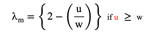
where u is measured rotor speed and w is reference rotor speed which is taken as w=2000 rpm.

In current and torque angle calculator [5]
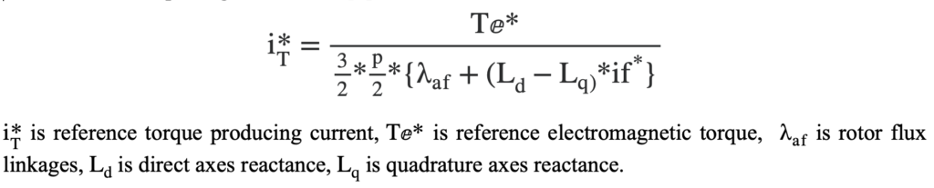
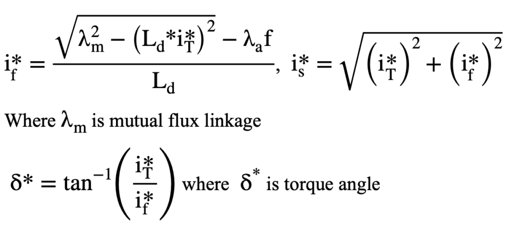
Reference stator flux (if*) and reference stator current (is*) [5] is given by
3. Results
3.1 Simulation results
In the present work, 8 Nm, 300 Volt dc and 2000 RPM speed PMSM motor is considered for simulation purpose.
In the figure below, the first waveform shows three phase current waveform of PMSM motor, denoted by Iabc (A). Second waveform is of speed, denoted by N (rpm). Third waveform is of generated electromagnetic torque, denoted by Te (Nm). Fourth waveform is of applied mechanical torque, denoted by Tm (Nm).
In figure 2, to follow reference speed i.e., 1000 rpm the measured speed is linearly increasing up to 1000 rpm at t =0.015 seconds and after that speed waveform is constantly following the reference speed. Initially developed electromagnetic torque (Te) is maximum i.e.10 Nm (as the maximum limit of PI controller is set to 10) and after reaching reference speed of 1000 rpm electromagnetic torque follows the applied mechanical torque i.e. Tm= 4 Nm. It can be seen that electromagnetic torque exactly follows the reference mechanical torque and accordingly three phase current waveform is varying.
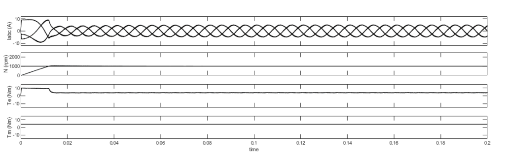
Figure 2. Steady state response at constant speed of 1000 rpm and torque of 4 Nm | Sterling Gtake E-Mobility Ltd
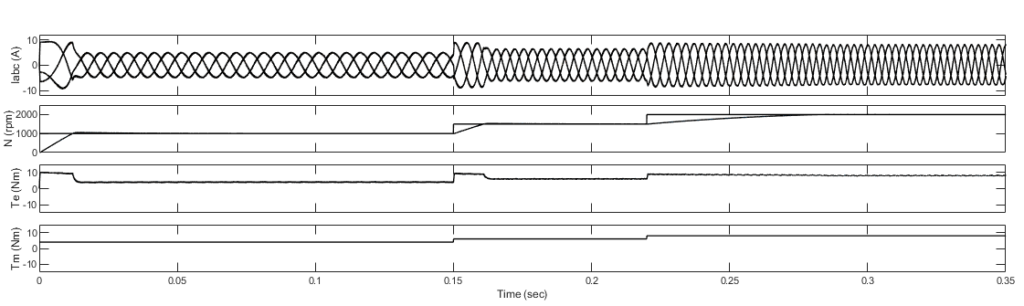
In figure 3, to follow the reference speed of 1000 rpm at t= 0.015 seconds, developed electromagnetic torque (Te) is maximum i.e.10 Nm and mechanical reference torque is increased from 4 Nm to 8 Nm and at t=0.15 seconds speed is increased to 1500 rpm, mechanical reference torque is increased from 6 Nm to 8 Nm and at t=0.22 seconds speed is increased to 2000 rpm. It can be seen that electromagnetic torque exactly follows the reference mechanical torque, and accordingly three phase current waveform is varied.
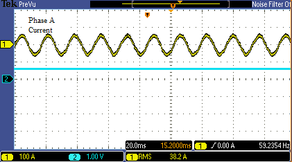
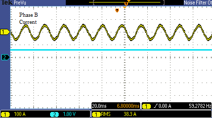
3.2 Experimental results
The experiment is performed for measuring three-phase voltage and speed for PMSM Motor of 8 Nm. Figures 4, 5 and 6 show steady state three-phase current waveform and speed, which is measured in rpm.

4. Conclusion
Field oriented control (FOC) of Permanent Magnet Synchronous Motor (PMSM) is modelled and performance is analyzed through simulation. Experiment is also performed for measuring three phase currents and speed. In modelling, the variation of speed and torque has been studied and the obtained results show the robustness of the FOC control. It can be observed from the results that the implemented FOC control for PMSM motor performs efficiently under all operating conditions.
About the author

The paper is authored by Sachin Singh – Manager R&D at Sterling Gtake E-mobility Ltd. manager R&D. His areas of interest include power electronics application to electrical machines and drives, power quality, sensorless control of PMBLDC motor and energy efficiency etc. The author can be reached at Sachin.Singh@sterlinggtake.com.
References
- P.Pillay, R.Krishnan, (1989). “Modeling, simulation and analysis of permanent magnet motor drives Part 11: The brushless dc motor drive,” IEEE Trans. Ind. Appl., vol. 25, no. 2, pp 150-185.
- P. Pillay and R. Krishnan, (1989). “Modeling, simulation, and analysis of permanent-magnet motor drives. I. The permanent-magnet synchronous motor drive,” IEEE Trans. Ind. Appl., vol. 25, no. 2, pp. 265-273.
- B.-K. Lee and M. Ehsani, (2001). “A simplified functional simulation model for three-phase voltage-source inverter using switching function concept”, IEEE Trans. Ind. Elect., vol. 48, no: 2, pp. 309-321.
- Nasser Hashemnia, Behzad Asaei,(2008). “Comparative study of using different electric motors in the electric vehicles,”IEEE Conference, Volume , Issue, 6-9.
- R. Krishnan, (2010). Permanent Magnet Synchronous and Brushless DC Motor Drives, CRC Press.
- A. Mishra, J. A. Makwana, P. Agarwal, and S.P. Srivastava (2012). “Modeling and implementation of vector control for PM synchronous motor drive”, IEEE, Int. Conf., Advances in Engineering, Science and Management (ICAESM)’12, pp. 582- 585.
- Jyoti Agrawal, Sanjay Bodkhe, (2014). “Modeling and Simulation of a Torque Controlled Permanent Magnet Synchronous Motor Drive,” IJERT, Vol. 3 Issue 3.
- Wenzhuo Chen; Wentao Jin, (2017). “A new model of the permanent magnet synchronous motor body,” IEEE, Conf, 15-17.
- Shadab Murshid, Bhim Singh, (2018). “Simulation and Hardware Implementation of PMSM Driven Solar Water Pumping System,” IEEE Trans. Ind. Appl., vol. 55, no.5, pp 4956 – 4964.
- Paramjeet Singh Jamwal,Sanjeev Singh,(2016). “Speed Controller Optimization for PMSM Drive Using PSO Algorithm.” Springer Science+Business Media Singapore, DOI 10.1007/978-981-10-0448-3_83.
Subscribe today for free and stay on top of latest developments in EV domain.


