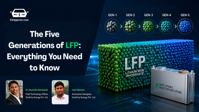
The Five Generations of LFP: Everything You Need to Know

From Mass-market to Industry’s High-Performance Standard
Compaction density has quietly become the most important number on an LFP spec sheet – and the most misunderstood. Here is what separates a Gen-2 cell from a Gen-5, why the physics of fast charging is hard to beat, and how China’s July 2025 export controls have redrawn the map for every non-Chinese cell manufacturer. -By Dr. Ravindra Kempaiah (CTO), Joel Manore (Designer), Zenfinity Energy Pvt. Ltd.
A chemistry, not a product
Every week, someone in the energy storage industry uses the phrase “LFP battery” but there are multiple generations within this “LFP battery” category depending on the cathode formulation.
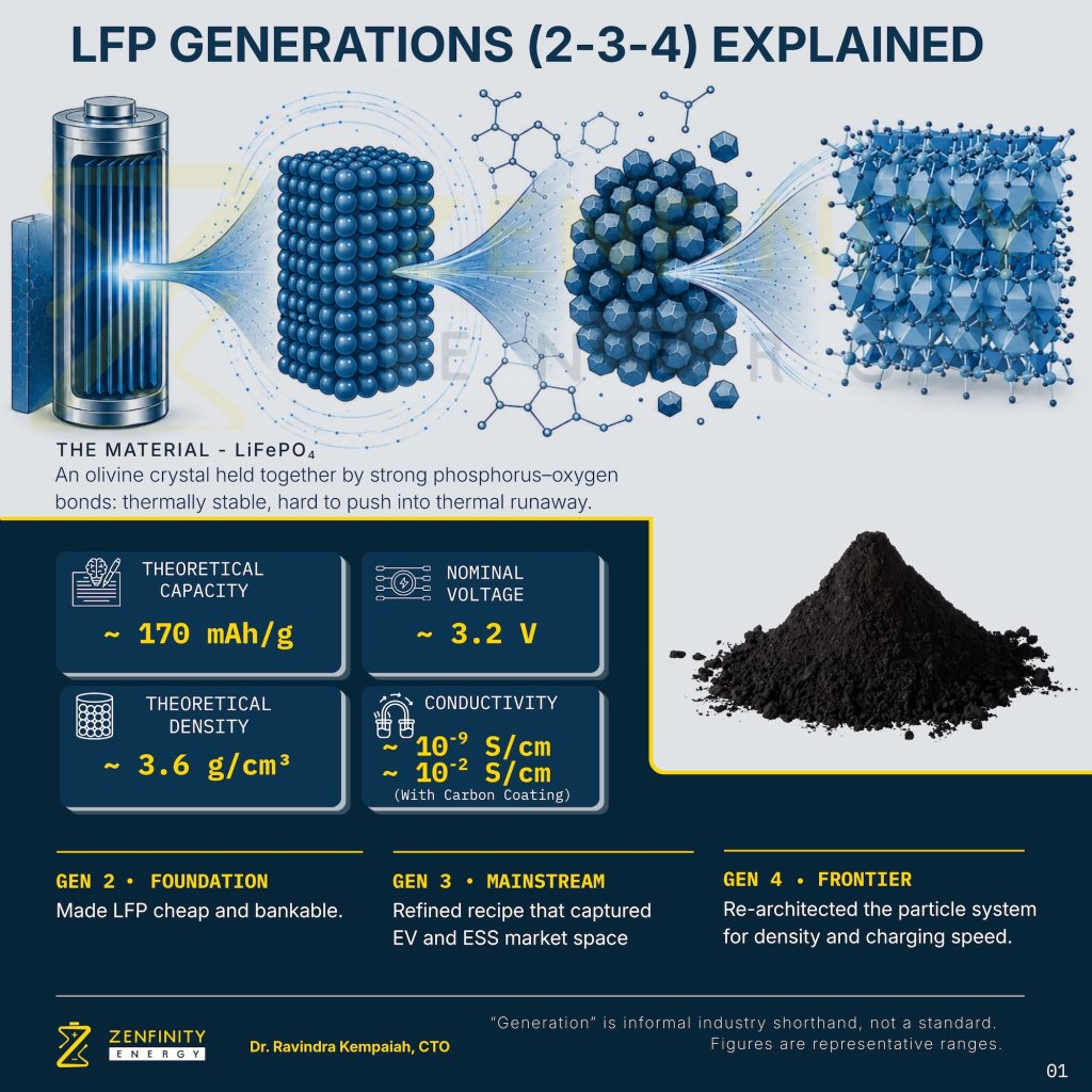
LFP – lithium iron phosphate – is a chemistry. LiFePO₄ at the particle level is an olivine crystal structure with 3.2 V nominal voltage. LFP has safety characteristics rooted in strong phosphorus–oxygen (P-O) bonds that make the material thermally stable and difficult to push into thermal runaway. These properties do not change from one manufacturing generation to the next. What changes are the energy density, the internal resistance, and the fast-charging capability.
There are now five distinct generations of manufacturing evolution – each representing a measurable leap in material processing, particle engineering, and system-level integration. A Gen-2 cell and a Gen-5 cell share an identical chemical formula but the performance gap between them is larger than the gap between entry-level and premium NMC chemistry.
Most engineers, integrators, and R&D teams working with LFP today are not aware this distinction exists. The industry has grown faster than the collective technical knowledge. This piece is an attempt to close that knowledge-gap and educate the growing ecosystem.
What “generation” actually means in LFP
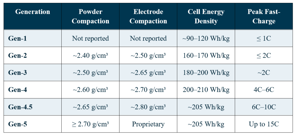
A generation shift in LFP is not a change to the crystal. It is a change to how the crystal is processed, packed, and engineered at the particle level. The single defining metric across all generations is compaction density – the mass of active cathode material packed per unit of electrode volume.
Because LFP has a lower intrinsic theoretical material density (3.60 g/cm³) than nickel-based chemistries like LiNiO2 (4.8 g/cm³), increasing compaction density is the central engineering lever that closes the energy density gap. Every generation represents a measurable advance on that lever – but arrived at through improved process. However, with Gen-5 reaching powder compaction density of ≥2.70 g/cm³, it must be noted that practical manufacturing methods cannot achieve perfect theoretical density of 3.60 g/cm³.
An important qualification before the numbers: these generations are informal industry shorthand, not a formal standard. Two Gen-3 cells from two different manufacturers will differ meaningfully in their exact compaction density, electrolyte formulation, binder chemistry, additive package, and sintering profile. The way particle size distribution is tuned across kiln temperature zones alone can shift a cell’s performance envelope by 10 to 15 percent on any given metric. The generation label captures the process discipline and the resulting performance band. It does not capture the manufacturer-specific art embedded in every step of the production line.
Gen-1: the origin
Gen-1 is the historical foundation on which everything that follows is built. It refers to the earliest LFP cathodes produced shortly after LiFePO₄ was identified as a viable lithium-ion cathode by Prof. John B. Goodenough and co-workers at the University of Texas at Austin in 1996–97. These first-generation materials were micron-scale, undoped, and uncoated, with intrinsic electronic conductivity so poor (on the order of 10⁻⁹ S/cm) that practical rate capability was extremely limited. The breakthrough that made LFP commercially usable came from Michel Armand, Michel Gauthier, and colleagues at Hydro-Québec and the Université de Montréal, who pioneered conductive carbon coating on nano-sized LFP particles, a route that raised effective conductivity by several orders of magnitude and unlocked the material’s use in real cells. Gen-1 was never a mass-market product in the modern sense; it is the pre-industrial base case against which every later generation’s compaction, coating, and particle-engineering advance is measured.
Comparative overview: Gen-1 through Gen-5
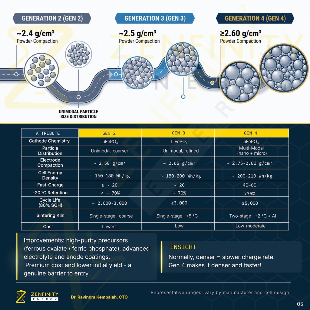
Gen-2 and Gen-3: the foundation and the current mainstream
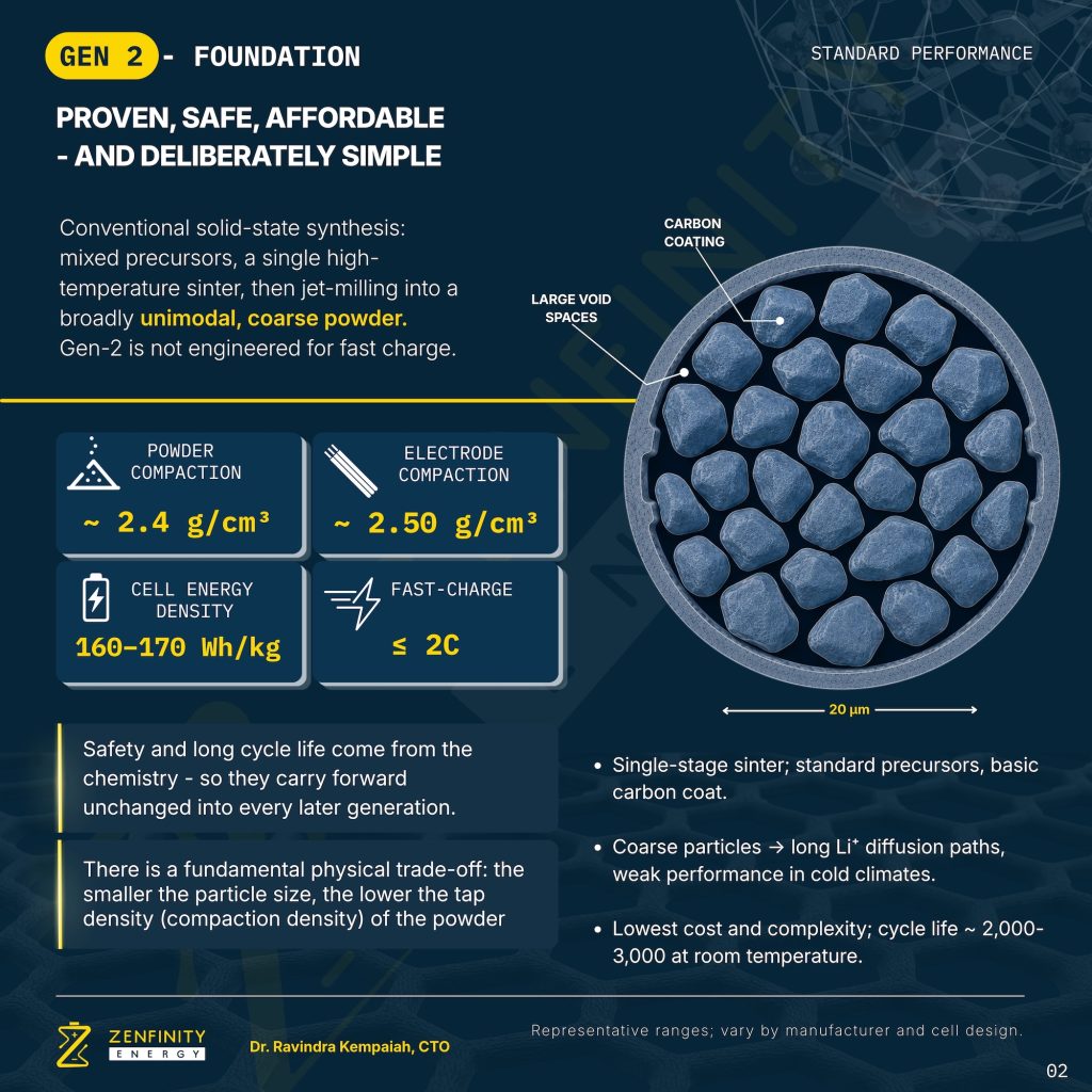
Gen-2 – Foundation
Gen-2 is built on conventional solid-phase synthesis. Precursors are mixed, subjected to a single high-temperature sinter, and jet-milled into a broadly unimodal, coarse powder. It is deliberately simple and not engineered for fast charge. Companies like Shenzhen Dynanonic (德方纳米, listed as 300769.SZ) have historically used solid-state routes, though they have shifted toward what is often called “liquid-phase” or “carbothermal reduction” methods over time. Shenzhen Dynanonic has been a supplier to Tier-1 cell makers like CATL, and EVE.
In Gen-2, the coarse particles create long lithium-ion diffusion paths – adequate for small-capacity storage at modest C-rates but limited in cold climates where diffusion slows further. At room temperature, cycle life sits at 2,000 to 3,000 cycles. Capacity fades as a result of loss of active material, solid-electrolyte interphase (SEI) growth, and electrolyte degradation, among other parasitic reactions.
Carbon coating is present but typically non-uniform. Because the coating precursor is dry-mixed with LFP precursors before sintering, coverage on individual primary particles is inconsistent. You often see 1.5–2.5% total carbon content with significant patches of bare LFP surface exposed to electrolyte. This is a major reason for the poorer high-temperature cycle life: bare Fe²⁺ surface sites dissolve into the electrolyte more readily. Cell energy density lands between 160 and 170 Wh/kg. Cost and complexity are the lowest across all generations.
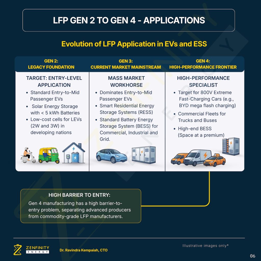
Gen-2 made LFP commercially viable at scale. It remains relevant today in cost-constrained applications: low-cost cells for two- and three-wheelers in developing markets, small-format solar storage under 5 kWh, and entry-level residential systems where there is price sensitivity.
Gen-3 – Refinement, not reinvention
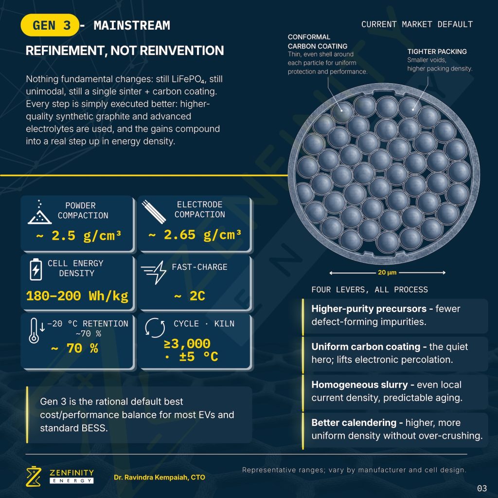
Gen-3 changes nothing fundamental. It is still LiFePO₄. It is still a unimodal particle distribution. It is still a single sinter with carbon coating. Every step is simply executed better – and the gains compound to offer significant enhancement.
Four process levers define Gen-3:
- Higher-purity precursors. Feedstock purity greatly influences cycle life. Gen-3 producers moved to reagent-grade iron, lithium, and phosphate precursors with tightly specified impurity limits, particularly for the transition metal contaminants (Cu, Ni, Cr, Zn) and moisture that catalyzes irreversible degradation in olivine LFP. Every PPM of contamination excluded from the feedstock is one fewer nucleation site for parasitic side reactions, Fe²⁺ dissolution, and destabilization over the cell’s operating life.
- Conformal carbon coating on nano-LFP. Carbon coating is applied through more controlled routes – either dissolved organic precursors that infiltrate a spray-dried precursor before pyrolysis, or two-step coating processes. Coverage is more conformal, thickness is more uniform (typically 1–3 nm), and total carbon content is often lower (0.8–1.5%) while still delivering better conductivity because coverage is higher quality.
- Homogeneous slurry. Even local current density during coating and calendering. Predictable aging. No hot spots. No cold spots.
- Better calendering. Higher compaction density achieved without over-crushing the coated particles. This is the difference between good process control and great process control.
The result: 180–200 Wh/kg at the cell level, ≥3,000 cycles to 80% state of health, and approximately 70% capacity retention at −20 °C. Sintering kiln temperature tolerance tightens to ±5 °C.
Gen-3 is the rational cost-performance default for most passenger EVs and standard grid BESS deployments today. It is what the current mass market deploys in GWh-scale.
Gen-4: where manufacturing becomes a precision discipline
Gen-4 is where substantial improvements arrive in fast charging and cold-weather performance. Where Gen-3 delivered its gains through incremental process refinement, Gen-4 delivers them through architectural redesign of the particle system itself. This is the generation where LFP manufacturing crosses from bulk chemistry into precision materials engineering – and where the barrier to entry becomes substantial rather than incremental.
Particle gradation technology
The single defining shift in Gen-4 is particle gradation. Rather than producing a bulk powder of similar-sized particles, Gen-4 manufacturers engineer a precise multi-modal distribution: nanoparticles are positioned strategically within the interstitial gaps between larger particles.
The geometry matters. A unimodal packing of spheres – even perfectly packed – leaves roughly 26 percent void space. A carefully designed multi-modal distribution can push that void fraction below 15 percent. That is where the compaction density gain comes from. Critically, it is achieved without the mechanical stress that crushes individual particle surface coatings – the failure mode that limits how far you can push a Gen-3 process with pressure alone.
Precursor evolution
The precursor chemistry also shifts in Gen-4. Manufacturers increasingly move from the conventional hydrated iron phosphate route toward the ferrous oxalate synthesis route. Ferrous oxalate delivers tighter, more uniform particle size distribution – but it is more demanding to handle due to lower stability in ambient air. Handling protocols tighten and the process complexity rises. So does the barrier to entry.
The cathode preparation process chain
It is worth naming, in one place, the full sequence of process steps that turn precursors into a finished LFP cathode powder. Each step is a potential defect source and a potential yield loss. In Gen-4 manufacturing, each step is also independently instrumented and controlled.
- Mixing – precursors combined under controlled atmosphere and stoichiometry.
- Sanding systems – wet milling to break down agglomerates and achieve target particle size before drying.
- Spray drying – controlled evaporation forms uniform precursor granules.
- Sintering – the crystallisation step. Gen-4 uses two-stage sintering: first stage forms the crystal; second stage densifies it. Kiln temperature tolerance tightens from ±5 °C in Gen-3 to ±2 °C in Gen-4.
- Secondary crushing – controlled fracture back to target particle distribution without damaging the carbon coating.
- Impurity refinement – including precise magnetic impurity removal.
Magnetic impurity removal – the underappreciated process
Magnetic impurity removal is one of the most consequential and least discussed steps in high-generation LFP manufacturing. Trace ferromagnetic contamination from iron, nickel, and chromium particles introduced through equipment wear, precursor handling, or transport, can migrate to the cathode-electrolyte interface during cycling and eventually cause micro-shorts inside the cell. At Gen-4 and Gen-5 compaction densities, where inter-particle spacing is already minimised, the tolerance for magnetic contamination is minimal. Modern high-precision LFP lines therefore include multi-stage electromagnetic separation for the cathode powder, and equivalent treatment for graphite anode material. Removing these impurities at the PPB level is a prerequisite for reaching fast charging and safety targets that define Gen-4 and above.
The physics trade-off Gen-4 must beat
Higher tap density slows fast charging rate. It is a physical limitation.
The trade-off between tap density and charge rate is fundamental. As the porosity between particles is reduced to increase volumetric density, the surface area available for electrolyte wetting decreases and ion transport is restricted. Polarization rises during discharge and the operating voltage can drop under load, leading to hysteresis. Simply pushing tap density up without addressing this side of the equation produces a denser cell that charges slower and delivers less usable energy under real duty cycles.
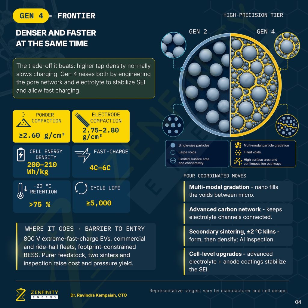
Gen-4 resolves this by engineering artificial ionic pathways through the electrode structure – designed channels that preserve electrolyte access to the interior of the multi-modal packing. Combined with advanced electrolyte formulations and thin anode-side coatings that stabilise the solid-electrolyte interphase, this is what allows Gen-4 to reach 4C–6C fast-charge rates at 2.60 g/cm³ powder compaction – a combination that was not physically achievable in Gen-3.
This capability – the simultaneous engineering of density and ion transport – is precisely what cannot be replicated by process substitution. It is also precisely what China’s July 2025 export controls placed behind a technology license.
Gen-5: LFP crosses into NMC performance territory
Industry leaders CATL and Gotion have both confirmed cell-level energy densities of 205 Wh/kg with their Shenxing Plus III and G-Ker II batteries respectively. That number matters because 200 Wh/kg was the threshold the industry associated with mid-nickel NMC chemistries. LFP was supposed to be the safe, cheap, cycle-life-heavy option that came with a permanent energy density penalty. Gen-5 breaks that assumption.
But energy density is not what makes Gen-5 remarkable. What makes it remarkable is that the density gains and the fast-charge gains and the cold-weather gains have arrived simultaneously, from coordinated improvements at four different layers of the cell. An engineering stacking of functional gains.
The four coordinated layers of Gen-5 improvement
Nanoscale LFP primary particles have been standard since Gen-2, and improved carbon coating and doping have progressed through Gen-4. What distinguishes Gen-5 is not any single breakthrough at the material level, but the coordinated integration of incremental gains across four subsystems: cathode, anode, electrolyte, and cell architecture, that together unlock sustained ultra-fast charging without the cycle-life penalty that would have accompanied the same C-rate targets in Gen-4.
1. Cathode: refined nano-LFP with advanced doping and coating uniformity
Gen-5 cathodes build on the nano-primary-particle foundation of Gen-3 but push further on three axes:
- Hierarchical particle architecture that combines nano-primary particles with engineered secondary morphology for higher tap density and better electrode processing;
- Advanced electrolyte additives for more stable SEI and more uniform carbon coating coverage at lower total carbon content, freeing mass fraction for active material; and
- Cation doping strategies that modify grain boundary conductivity and suppress Fe²⁺ dissolution. These refinements of Gen-4 processes result in a cathode that maintains rate capability without sacrificing the specific capacity gains of prior generations.
2. Anode: engineered graphite architecture that raises the lithium plating threshold
This is where the largest Gen-5 gains sit. A cathode capable of delivering high C-rates is useless if the anode cannot absorb the incoming lithium without Li-plating / dendrite formation. Gen-5 anodes use engineered graphite particle morphologies and electrode structures, CATL’s Shenxing III anode architecture being the most-cited example, that reduce local overpotentials, improve Li⁺ transport pathways, and raise the current density at which plating would initiate. Silicon-carbon composite anodes are being scaled in parallel, Gotion’s G-Ker II and G-Qing batteries are clear market signals, but flagship Gen-5 fast-charge implementations rely primarily on graphite architecture rather than silicon, because silicon’s volumetric expansion and cycle-life penalties remain unresolved at high C-rates and extended calendar aging during the life of an EV.
3. Electrolyte: formulations engineered to maintain SEI integrity under high-rate stress
The SEI forms at the anode surface during the first cycles of a cell’s life. Its mechanical and chemical stability determines both cycle life and safety margin under fast-charge conditions, where the SEI is most vulnerable to fracture and re-formation. Gen-5 electrolyte formulations use additive chemistry and, in some cases, semi-solid architectures that stabilise the SEI through aggressive cycling, restricting the parasitic reactions that would otherwise consume active lithium and increase interfacial resistance leading to capacity fade.
4. Cell architecture: internal resistance minimised at every joint
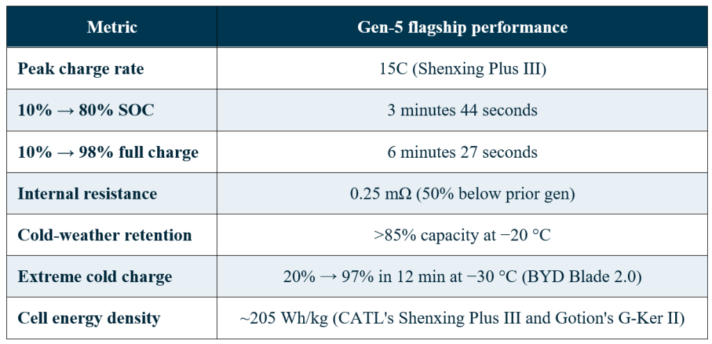
CATL’s Shenxing III platform reports a cell-level internal resistance of 0.25 mΩ, roughly ~40 to 50% lower than Gen-3. This is achieved through the accumulation of small gains: current collector geometry, foil selection, tab and busbar design, and systematic elimination of resistive paths across every internal interface. Combined with targeted cooling at the cell’s most thermally sensitive regions, the low-resistance architecture is what allows the platform to sustain peak C-rate of 15C without catastrophic heat generation.
The through-line: Gen-5 differentiation is not just chemistry-driven. The cathode chemistry is a refinement of Gen-3/Gen-4 nano-LFP. What Gen-5 delivers is systems integration, matching cathode rate capability to anode absorption capacity to electrolyte stability to cell architecture thermal budget, so that no single subsystem becomes the limit. The engineering discipline is coordination, not invention.
The result, in numbers
The invisible enabler: AI-driven process control
None of the numbers in Table 2 are achievable without a manufacturing yield that is high enough to be commercially viable. This is the part of the Gen-4 and Gen-5 story that may be the most important one.
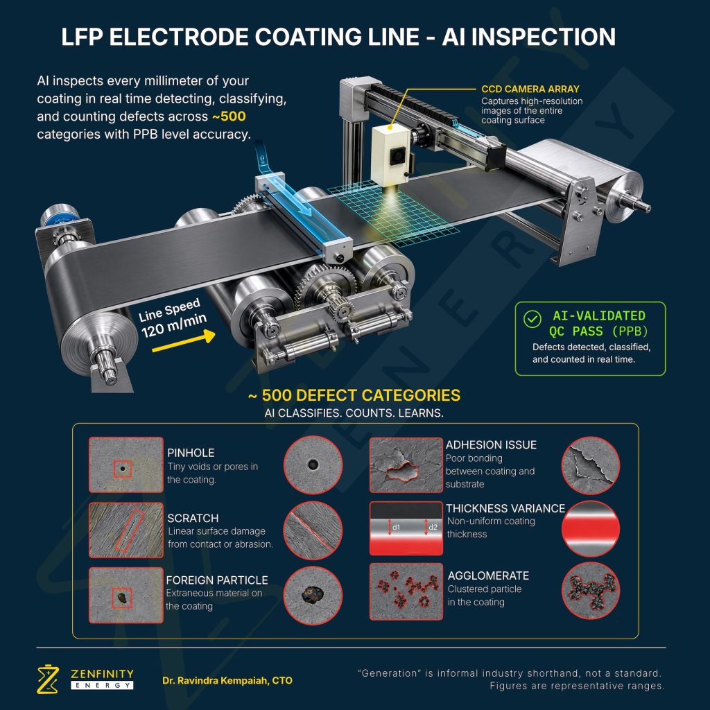
At Gen-4 and Gen-5 compaction densities, the tolerance for defects in the electrode coating collapses. A pinhole, a scratch, a foreign particle embedded in the coating – any of these can create a local hot spot, a short circuit path, or a nucleation site for lithium plating during fast charging. Defects that would have been benign in a Gen-2 electrode become failure-mode initiators in a Gen-5 electrode.
The problem is compounded by production speed. In high-throughput cell manufacturing, the coating rollers run at approximately 120 metres per minute. No human inspector can process defect information at that rate. Traditional statistical sampling – pulling a coupon every fifteen minutes and inspecting it under a microscope – misses the vast majority of what crosses the line.
CATL’s visual AI approach
CATL has responded to this by deploying high-resolution charge-coupled device (CCD) camera arrays combined with visual AI classifiers [CATL official video] along the coating and assembly lines. The system is trained to identify approximately 500 distinct defect types – pinholes, scratches, foreign particles, edge irregularities, coating thickness variations, adhesion failures, and dozens more – in real time at line speed, in a role similar to that of Thermo Fisher’s LInspector device.
The performance target is parts-per-billion (PPB) defect rates. That is not a typo. Achieving PPB-level outgoing quality at 120 metres per minute of coating throughput requires that the inspection system catches defects reliably at rates the human eye cannot even register in a still image. This is what makes Gen-4 and Gen-5 volumes commercially viable rather than academically interesting.
Visual AI is also used further upstream, monitoring particle morphology and metrology directly. The system verifies that the multi-modal particle distribution coming out of the mill matches the target specification – the geometry that Gen-4 and Gen-5 packing depends on. If the distribution drifts, the process is corrected before the drift ever reaches the coating line.
The advanced particle chemistry enables high compaction density. Visual AI improves manufacturing yield at scale.
One distinction the industry consistently conflates
Generation and chemistry are two independent axes. Confusing them leads directly to specification errors.
Compaction generations track a manufacturing trajectory – how efficiently the LiFePO₄ crystal is packed into an electrode. LMFP – lithium manganese iron phosphate – is a chemical substitution where manganese replaces a portion of the iron in the crystal lattice, raising the voltage platform from 3.2 V to approximately 3.8 V. Higher voltage means higher energy density, arrived at through fundamentally different physics. These are complementary developments, not competing ones. The next inflection point in LFP-family chemistry is expected to combine high compaction densities (≥2.70 g/cm³) with NMC or LMFP voltage platforms – a Gen-5+ material with an intrinsically higher voltage. Any R&D or engineering team evaluating cells against future specifications needs to understand both axes independently.
Application mapping: where each generation fits
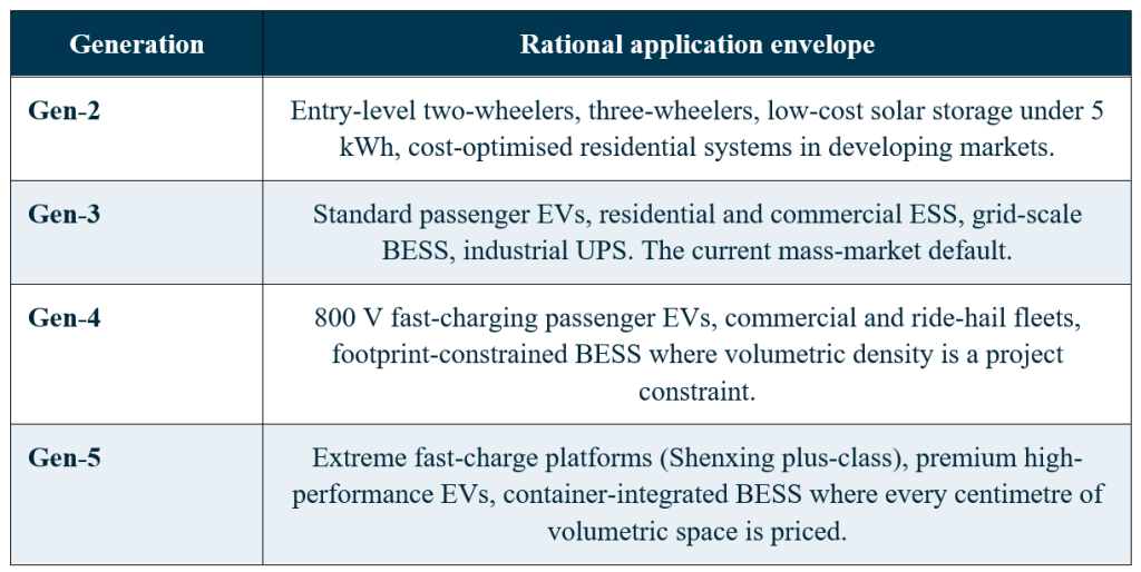
Each generation has a rational application envelope. Specifying above it wastes capital; specifying below it produces field problems that surface only after commissioning.
Two amplifiers deserve mention. Cell-to-Body (CTB) and Cell-to-Pack 3.0 (CTP 3.0) architectures increase volumetric space utilisation from the traditional 65 percent to approximately 76 percent, further raising system-level energy density and reducing non-active component weight by around 27 percent. When a Gen-5 cell is deployed in a CTB pack, the delivered system-level energy density is meaningfully higher than the cell-level number alone would suggest. Specification benchmarks should therefore always name both the cell generation and the pack architecture.
China’s export controls: the geopolitical layer
The entire discussion above assumes a manufacturer can, in principle, build any generation of LFP they have the capital to fund. Through 2025, that assumption stopped being true for Gen-4 and above.
The July 2025 controls (active)
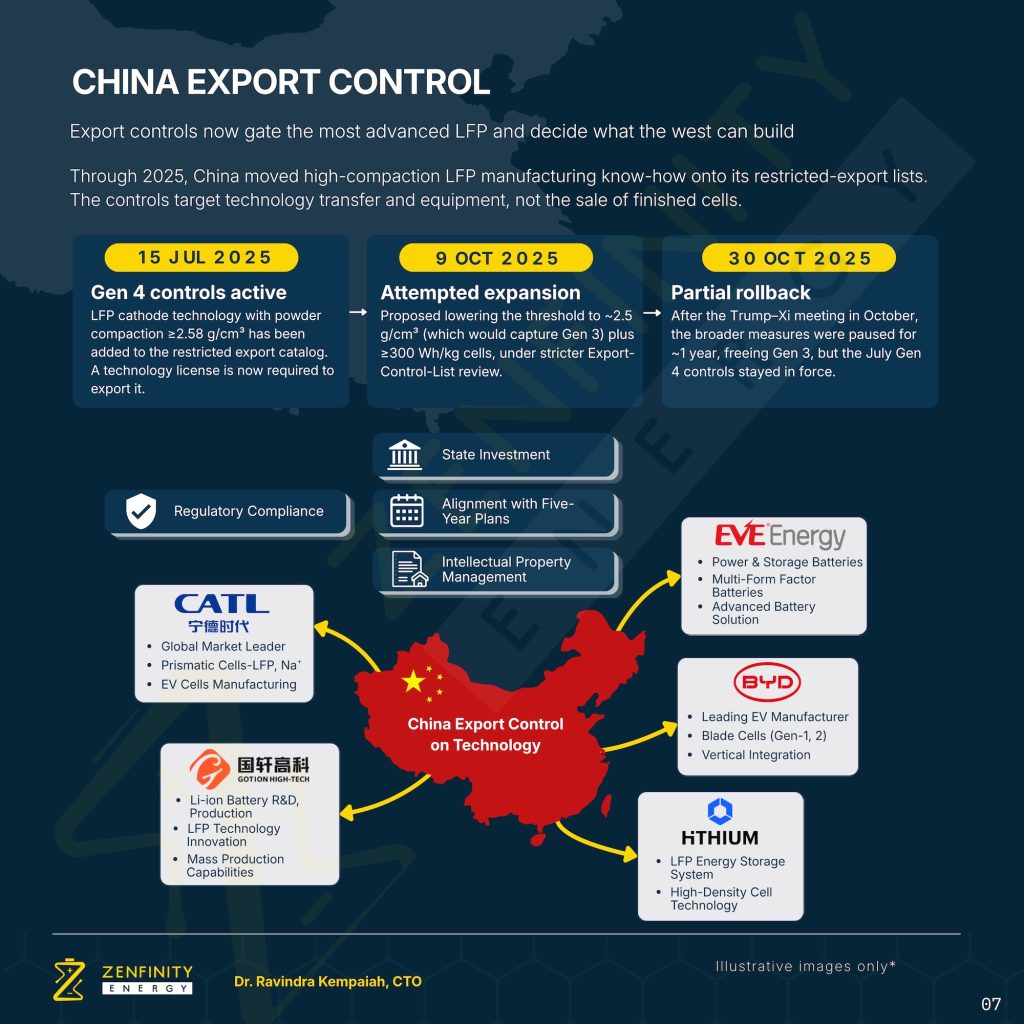
On 15 July 2025, China’s Ministry of Commerce added LFP cathode manufacturing technology to the Foreign Trade Law’s catalog of restricted exports. The controls target LFP powders with a compaction density of ≥2.58 g/cm³ – a threshold that isolates Gen-4 and above while leaving Gen-2 and Gen-3 unrestricted.
Exports of the covered technology now require a Technology Export License, granted after severe scrutiny of contracts and joint venture agreements by provincial commerce and science departments. Critically, the controls target the manufacturing know-how and specialised equipment – high-precision roller-hearth kilns, particle gradation lines, AI-driven inspection systems – not the sale of finished cells. Chinese cells continue to ship. The capability to make them domestically outside China does not.
The October 2025 expansion (attempted)
On 9 October 2025, the Chinese government proposed lowering the compaction threshold to ≥2.5 g/cm³ – a move that would have captured Gen-3 as well as Gen-4 – and adding an energy density threshold at ≥300 Wh/kg for finished lithium-ion cells. This proposal was moved to the Export Control List, which involves oversight by the Central Military Commission and represents a significantly more restrictive tier of controls.
The October 2025 partial rollback
Following the meeting between the US and Chinese leadership on 30 October 2025, the broader October expansion was suspended for approximately one year. Gen-3 technology was released from the export control regime. However – and this is the point that matters for procurement and industrial policy planning – the July 15 controls targeting Gen-4 (≥2.58 g/cm³) were not suspended. They remain fully in force.
What this means in practice
- Any OEM or cell manufacturer outside China attempting to source or replicate Gen-4 technology now faces a licensing hurdle that is, in practice, extremely difficult to clear.
- Even overseas projects fully owned by Chinese companies are reportedly finding it difficult to obtain the necessary export licenses to transfer equipment and process know-how out of China.
- The licensing process itself gives the Chinese government detailed visibility into global battery supply chains and joint venture partnerships.
- Gen-3 is the ceiling for practical non-Chinese localisation in the near term. Gen-4 and above will remain a Chinese-manufactured product for the foreseeable future, unless the July 15 controls are also negotiated down in a subsequent round of talks.
What this means for India
India will import a substantial volume of LFP cells over the next twelve months – a figure widely estimated in the industry at around 25 GWh, though the precise number varies by tracker. Projects spanning grid BESS, commercial and passenger EV fleets, industrial UPS, and residential solar storage will all draw from that import volume. The engineers, developers, policymakers, and financiers specifying and financing those systems are largely working without a shared framework for:
- Which generation of LFP is appropriate for their application.
- Which performance characteristics to demand contractually.
- What the supply chain now looks like after the July 2025 controls.
- What premium is justified for Gen-4 versus Gen-3 in each use case.
- How to write a specification that is testable at incoming inspection rather than accepted on datasheet alone.
The most important operational consequence of the export control regime is this: for procurement teams building grid-scale BESS or commercial EV platforms in India, Gen-3 is now the ceiling for practical localisation, and Gen-4 will remain a Chinese-supplied product. Both are viable. Both are appropriate for different applications. But they should not be confused with each other, and the price differential between them should be evaluated against a clear-eyed view of what the additional density and fast-charge capability actually deliver in the deployed application.
The technology export control is already happening in India: JSW has put its 50 GWh LFP cell manufacturing plant on hold because of China’s export controls.
A closing note
The five generations of LFP represent one of the more remarkable engineering trajectories in the history of commercial battery manufacturing. In roughly a decade, an inexpensive, safe, cycle-life-heavy chemistry that industry consensus dismissed as unable to compete with nickel-based cells on energy density has systematically closed that gap, then closed the fast-charging gap, then closed the cold-weather gap – and done so while maintaining the safety characteristics that made it attractive in the first place.
For an industry accustomed to treating LFP as a single, undifferentiated product, the practical implication is that this treatment no longer works. The generations are informal shorthand. The engineering distinctions they encode are real. And the export control regime that now governs the boundary between them will shape the global battery supply chain through the end of this decade.
The task for anyone specifying, procuring, integrating, or financing energy storage in India is to internalise this framework and use it. That is what technical education infrastructure is for.
About the authors

Dr. Ravindra Kempaiah is Chief Technology Officer at Zenfinity Energy Pvt. Ltd., headquartered at IIT Madras Research Park. Dr. Kempaiah was a post-doctoral researcher at Dalhousie University under Dr. Jeff Dahn and holds a Ph.D., in Mechanical Engineering from the University of Illinois, Chicago. His work spans battery materials science, cell chemistry, and field-deployment engineering across residential, commercial and industrial, and grid-scale energy storage applications.

Joel Manore is an Animation Designer and a creative professional at Zenfinity Energy Pvt. Ltd. With a passion for animation and visual storytelling, he brings complex ideas and emerging technologies to life through engaging visuals. His work focuses on making technical concepts simple, clear, and accessible to a wider audience.
Zenfinity Energy operates a Battery R&D Lab at IIT Madras Research Park and is a recipient of the Karnataka ELEVATE Nxt Deep-tech grant.
Also read: How to spot counterfeit LFP cells before they destroy your BESS project
Subscribe & Stay Informed
Subscribe today for free and stay on top of latest developments in EV domain.