Ola Electric 2W Battery Pack Tear Down
This guest post has been contributed by XLEX Batteries.
1. Introduction
Ola Electric has rapidly positioned itself as one of the most influential players in India’s electric two-wheeler revolution. Beyond the scooters themselves, a critical pillar of Ola’s strategy is its in-house battery technology, which serves as the backbone of its product roadmap and cost leadership ambitions. The company has invested heavily in vertical integration — from developing battery packs at scale to building its own cell manufacturing gigafactory in Tamil Nadu — signalling its intent to dominate not just the EV market but the broader energy ecosystem in India.
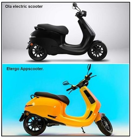
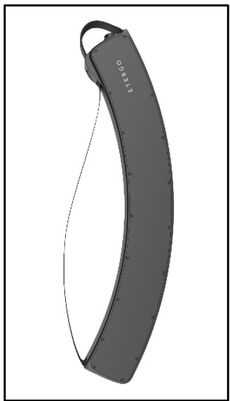
From left to right: OLA’s S1 Battery Pack, OLA’s vehicle DNA acquired from Etergo, Etergo’s banana battery pack
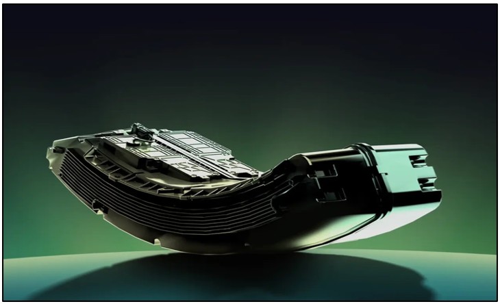
Ola Electric’s scooter packs are some of the most distinctive in the Indian EV landscape. With a banana-shaped custom enclosure and a 14S16P 21700 cylindrical cell configuration, they represent an aggressive optimization of packaging, cost, and manufacturability. Few people know that Ola Electric’s battery (as well as the vehicle) DNA traces back to Etergo EV, a European startup it acquired in 2020. Etergo’s innovative banana-shaped swappable battery pack became the foundation for Ola’s current design approach. The similarities in pack geometry highlight how strategic acquisitions can accelerate EV product development by bringing proven IP and design ideas in-house. This teardown documents the internal structure, interconnections, thermal design, and battery management system (BMS).
2. Pack Fundamentals
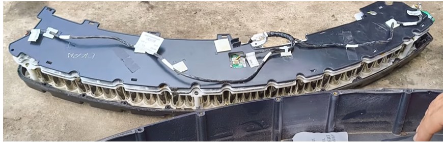
Ola Electric scooter battery pack is built around LG 21700 NMC cylindrical cells, each rated at approximately 4.8 Ah. These cells are arranged in a 14-series by 16-parallel configuration (14S16P), resulting in a total of 224 cells. This setup provides a nominal pack voltage of around 51.8 V and an overall energy capacity of about 3.9–4.0 kWh.
To house this configuration, Ola uses an Etergo inspired custom-molded plastic enclosure with a distinctive “banana” shape. Unlike conventional rectangular housings, this curved enclosure has been designed specifically to fit into the scooter’s underfloor chassis cavity, maximizing available space while keeping the center of gravity low. The enclosure not only defines the pack’s unique footprint but also contributes to structural rigidity and thermal interface alignment within the vehicle platform.
It is important to note that while the present packs rely on LG 21700 cells, Ola has publicly announced its move toward localizing cell production. The company is developing its own Bharat Cell manufacturing line, which is still ramping up and has yet to reach scaled output. In the interim, Ola is expected to continue sourcing cells from established suppliers such as LG to support its production volumes. Looking forward, Ola has also indicated plans to transition to larger-format 4680 cells, aligning with global industry trends in high-energy-density pack design.
3. Module Architecture
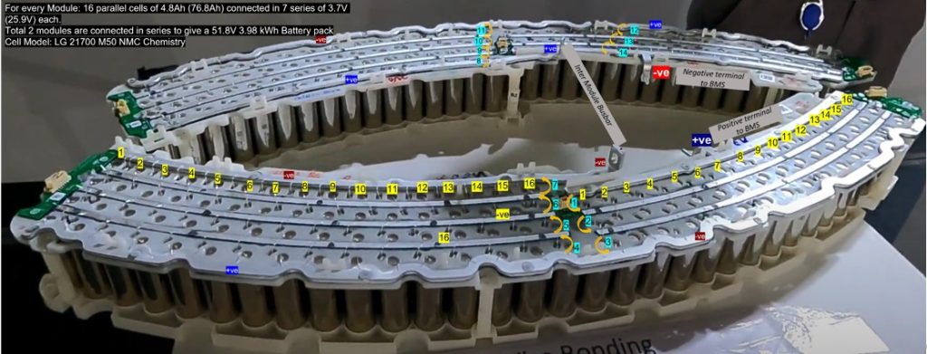
Ola’s Battery Pack series parallel configuration reverse engineered by XLEX Engineers. Source: xlex.in
Internally, the 224-cell array is divided into two modules, and each module is further split into two halves for optimized interconnection. In each module, the first half follows a 16P3S arrangement, while the second half follows a 16P4S arrangement. These halves are connected laterally to form a 7-series block per module.
The second module mirrors the first, and both modules are connected in series to complete the pack’s 14S string. This is achieved by linking the negative terminal of the first module directly to the positive terminal of the second module, with the “U-turn” connection at the far end finalizing the series loop. This mirrored modular structure simplifies current collection and ensures compact routing of busbars and interconnects.
All cells are oriented in the same direction, which is a deliberate choice to standardize thermal and electrical connections. This uniform orientation allows the entire underside of the cell array to be coated with thermal interface material (TIM). Heat is then consistently extracted through the baseplate and the sidewalls of the enclosure, providing a controlled thermal pathway that balances efficiency with manufacturability.
4. Busbars & Interconnects
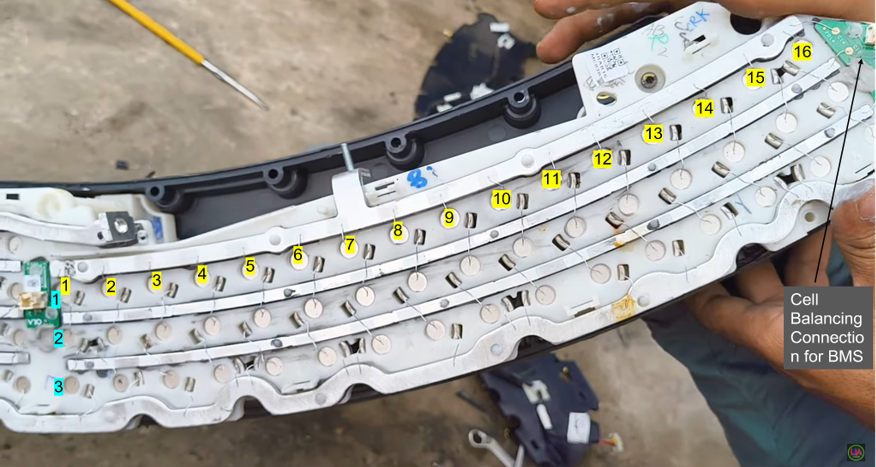
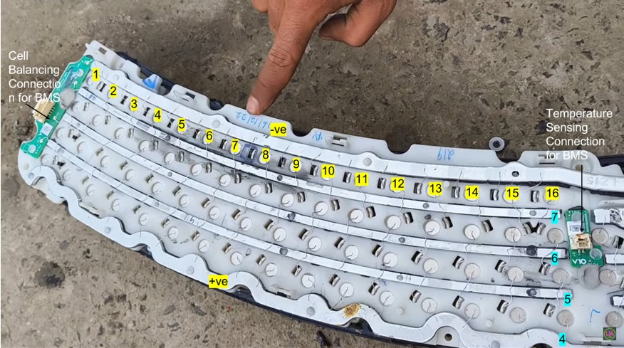
Image of module split showing the 16 cells arranged in 3S and 4S arrangement side by side. Source: YouTube
The electrical backbone of the pack is built around aluminium busbars, which provide the main series and parallel connections across modules. These busbars are bolted together at the centre of the pack. Interestingly, Ola has chosen ultrasonic wire bonding instead of traditional welded tabs for the cell-to-cell interconnections. This approach uses fine aluminium wires to link cells directly to the printed circuit boards, a method borrowed from consumer electronics and increasingly applied in EV packs for its precision and cost-effectiveness.
The custom white plastic holder has cutouts that expose only the necessary contact points for bonding, while insulating the rest of the cell surface.
Final power delivery is routed through two distinct blue busbars that are bolted onto the BMS board. From there, the current transitions to orange-colored busbars that form the main pack terminals. The output cables themselves exit the enclosure through nylon cable glands, which provide both strain relief and sealing against environmental ingress. The overall scheme reflects Ola’s attempt to balance manufacturability, electrical efficiency, and safety within a compact architecture.
5. PCBs Inside Each Module
Wiring harness design connecting the three PCBs on the module. Source: YouTube
Each of the two modules within the pack is supported by its own network of printed circuit boards. Along the sides of the modules, slim PCBs are connected to the 3S and 4S group terminals via wire bonds. These side PCBs handle voltage measurement and interconnection at the group level. A smaller central PCB runs through the module’s middle, which appears to be dedicated primarily to thermal monitoring by hosting temperature sensing points.
A wiring harness links the side PCBs and the central PCB, consolidating their signals before routing outward toward the main BMS. This harness is carefully insulated from the cell bodies by a thin plastic barrier to prevent electrical shorts or abrasion. The distributed PCB architecture allows Ola to connect all the series connections and multiple points within the module, feeding data back to the BMS for protection and balancing.
6. Thermal Management
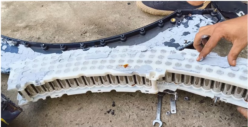
Thermal Interface Material (TIM) Paste seen on the bottom side of the module. Source: YouTube
One of the lesser-known aspects of Ola’s battery engineering is the way its cell-holder plastics are designed. These frames don’t just keep cylindrical cells in place; they also contribute to thermal management. Instead of standard insulating plastics, Ola uses a specially engineered polymer base with significantly higher thermal conductivity. This allows heat from the cells to transfer more effectively into the pack casing, rather than trapping it within the module.
The design is further supported by air-cooling features such as fins on the outer housing, which increase surface area and improve natural heat dissipation. Within the pack, thermal interface materials (TIMs) are used between the conductive cell bed and the enclosure to spread and channel heat more evenly.
While Ola hasn’t publicly disclosed the exact composition of this polymer, it is understood to be part of their proprietary IP. The material appears to be a thermally conductive composite—likely filled with additives or fibers that improve heat transfer without compromising mechanical strength. The result is a pack design that manages to keep temperature gradients low, ensuring cells operate within safer and more consistent ranges.
Notably, there are no liquid cooling plates or embedded channels within this design. Passive cooling is adequate for the city-duty cycles and average power demands of an electric scooter, but it limits the pack’s ability to sustain high discharge rates over extended periods. In essence, the system is designed for efficiency and cost control in urban commuting scenarios rather than for aggressive performance use cases.
7. BMS & Electronics
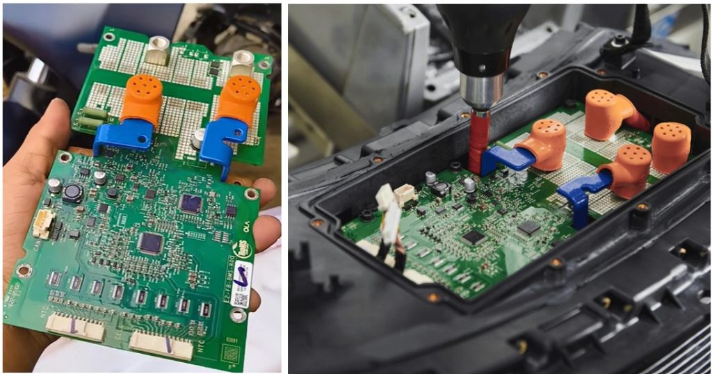
OLA BMS Board. Source: OLA official website and YouTube
The battery management system (BMS) sits at the heart of the pack and reflects Ola’s attempt at integrating multiple safety and control functions onto a consolidated board. High-voltage connections are handled by two blue busbars bolted directly into the BMS PCB, ensuring that large currents are managed with minimal resistance. Along the lower edge of the board, rows of MOSFETs can be seen (black packages at lower PCB edge) — these likely serve as the switching elements for charge/discharge control and safety protection.
At the center of the BMS lies the main microcontroller or system-on-chip, responsible for coordinating voltage monitoring, current protection, and communication with the vehicle. Linear resistor banks are also visible, suggesting that cell balancing is achieved through passive bleed resistors rather than active shuttling of charge. White connectors labeled with designations NTC and CELL interface the module-level harnesses to the BMS, bringing in data from temperature sensors and voltage taps across the pack. Around the periphery of the board, smaller ICs provide sensing, CAN communication, and gate driving for the MOSFETs. The result is a compact but robust system capable of handling both safety-critical operations and day-to-day management of the pack.
8. Safety & Enclosure Design
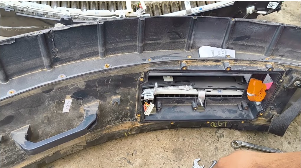
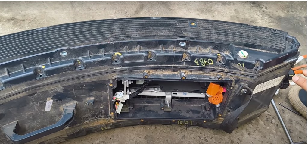
OLA Battery Pack enclosure with BMS and side cover sections removed. Source: YouTube
Mechanically, Ola has chosen to prioritize lightweighting and manufacturability in its pack design. The cells are housed within a white custom plastic holder that keeps them firmly aligned while exposing only the necessary areas for ultrasonic bonding. The enclosure itself is also plastic, which reduces mass compared to aluminium casings, but at the expense of some crash robustness.
Ingress protection is managed through the use of nylon cable glands and sealing layers around the housing, which provides a water- and dust-resistance rating equivalent to IP67 or higher. The insulation strategy within the pack — using selective plastic cutouts and barriers — ensures that electrical pathways are tightly controlled while minimizing the risk of shorts under vibration or moisture exposure. This focus on material efficiency and sealing underscores Ola’s aim to create a durable yet lightweight battery solution for mass-market scooters.
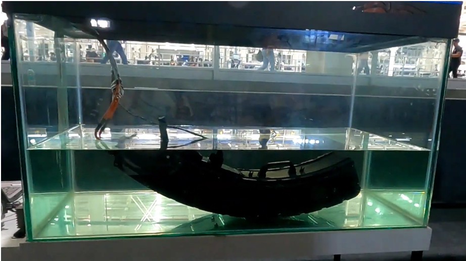
OLA’s battery pack is immersed in water. Source: Ola Factory Video
9. Observations & Insights
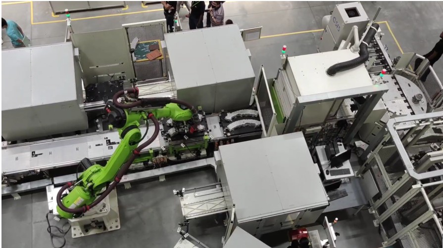
OLA Automated battery line showing a robot arm picking and placing the packs in and out of the station
The teardown reveals a design philosophy centered around cost efficiency and scalable manufacturing. Ola combines aluminum busbars with plastic housings and ultrasonic bonding to streamline assembly while reducing weight. The mirrored module architecture provides a straightforward way to achieve the 14S configuration, improving production efficiency and simplifying quality control.
Thermal management is intentionally low-cost and passive, sufficient for routine city rides but not designed for heavy-duty or performance-oriented applications. The distributed PCB monitoring system feeds into a robust BMS, which consolidates current handling, balancing, and protection into a compact architecture that balances safety with affordability. Overall, the choices made reflect Ola’s position in India’s rapidly growing 2W EV segment, where cost and scale are the dominant drivers.
10. Conclusion
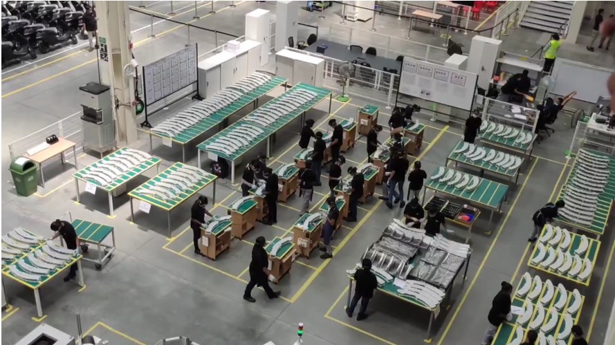
OLA Battery Assembly plant showing multiple work stations. Source: Ola Factory Video
Ola’s battery pack highlights the engineering trade-offs that define high-volume electric scooter manufacturing. On the positive side, the design achieves high energy density, a lightweight footprint, and a modular architecture that is efficient to assemble. These features align with Ola’s strategy of cost leadership and scalability.
However, the reliance on passive cooling, a plastic enclosure, and ultrasonic bonding introduces certain compromises. The thermal headroom is limited, making the pack less suitable for sustained high-power operation. Serviceability is reduced compared to packs with modular metal housings, and crash robustness is not as strong as that of aluminium-cased alternatives.
In summary, Ola has created a battery pack that reflects its market priorities: delivering affordable, scalable, and lightweight energy storage for India’s mass two-wheeler market. The design is less about premium performance and more about democratizing EV adoption at scale.
References
- Ola’s official website images and videos https://www.olaelectric.com/ev-hub
- Battery Design.net — Ola S1 Battery Breakdown (14S16P, LG 21700 cells) https://www.batterydesign.net/ola-s1/
- Ola teardown videos (YouTube, EV teardown community) —https://youtu.be/cWWB-dEgMHY?si=JxXy9kNHzNt7E7Se
- XLEX Batteries Reverse Engineering – https://xlex.in
- Ola S1 Pro: The Birth Of The Battery Pack, Zigwheels
About the author

Pranav Nagaveykar, Founder – XLEX Batteries Pvt Ltd
Pranav has over 12 years of experience in EV battery R&D. He has worked with leading OEMs, including TATA, FORD, and Maserati, and is also involved in solid-state battery research in Paris. At XLEX, he is building a deep-tech battery startup focused on innovative pack architectures, developing structural and immersion-cooled battery technologies specifically for lightweight electric vehicles.
Also read: Exploring Cell-to-Chases/ Cell-to-Body (CTC/CTB) designs for e-2Ws
Subscribe & Stay Informed
Subscribe today for free and stay on top of latest developments in EV domain.