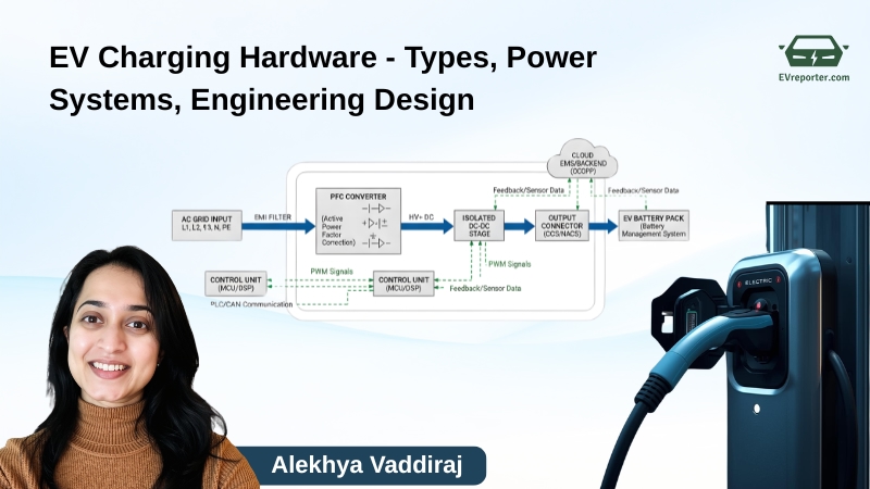
EV Charging Hardware Deep Dive | Types, Power Systems, and Engineering Design

EV CHARGING TECH SERIES by Alekhya Vaddiraj – PART 1
The Global Charge‑Up: Engineering the EV Power Backbone
Electric vehicle charging is more than plugging into a power source — it’s the interface where electrical engineering, battery chemistry, and digital control converge. This part of the series explores how different charger types work, their power conversion, architecture, and the engineering that makes modern charging fast, efficient, and safe.
The Foundation: How EV Charging Works
At its core, charging is the process of transferring electrical energy to the EV’s battery pack. The onboard charger (OBC) inside the vehicle dictates how much power it can accept and how it converts AC to DC, since all EV batteries store DC energy.
Core Components of an EVSE (Electric Vehicle Supply Equipment):
- Input Supply Module: Connects to grid power (AC mains, typically single- or three-phase).
- Power Conversion: Converts voltage and current to appropriate DC levels for the battery.
- Communication & Safety Interface: Negotiates current limits, monitors temperature, and ground faults
- Output Connector: Ensures compliant plug standards and locking mechanisms.
Charging = controlled flow of DC into the traction battery.
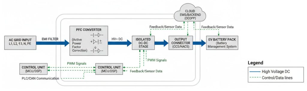
Inside every EVSE: input module → filtering → rectification/inversion → output DC bus → control logic.
Formula: power equals voltage times current; efficiency hinges on switching losses (∼ 2–5 %).
Engineering Architecture
EV chargers are essentially precision power‑conversion systems — turning alternating current (AC) from the grid into regulated, battery‑ready direct current (DC). Their backbone lies in high‑efficiency power electronics, designed for compactness, thermal management, and reliability over many thousands of cycles.
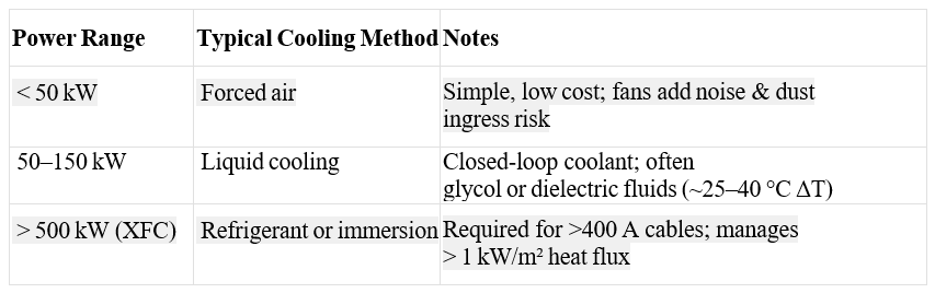
Charger Categories by Power
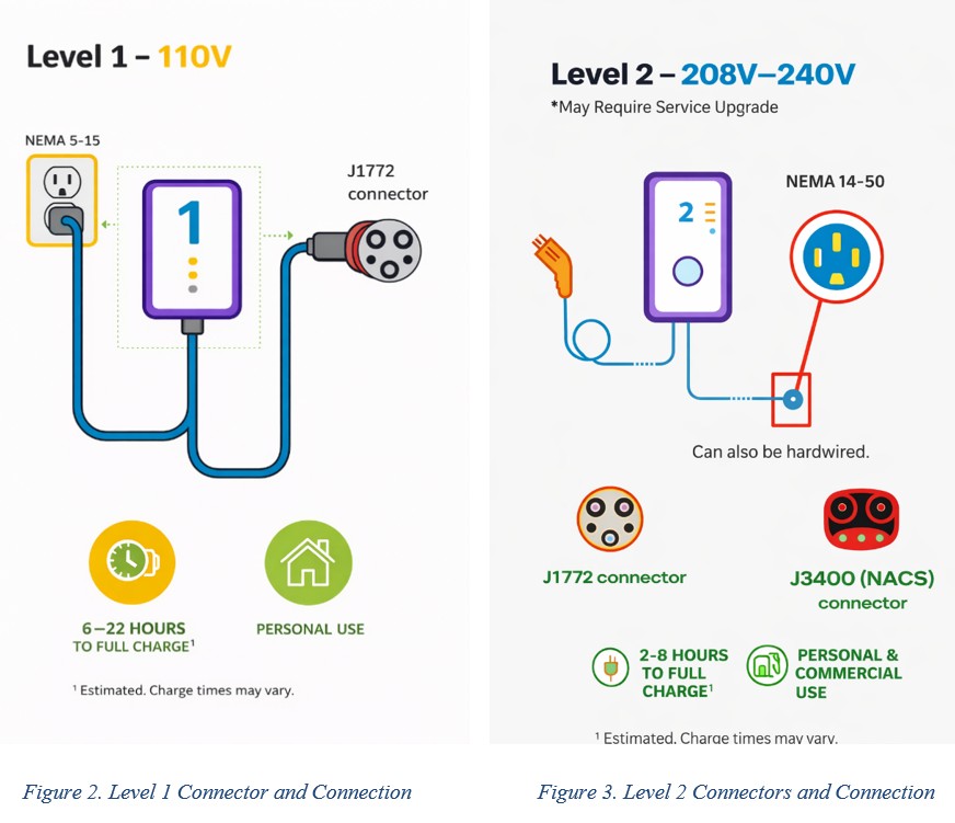
Level 1:
- Also known as Type Ⅰ or AC level I
- charging through a 240V (single phase) household outlet in India or a common residential 120-volt (120V) AC outlet in the US.
- Uses SAE J1772 connector
- Assumes 1.9 – 3 kW charging power range ideal for overnight charging
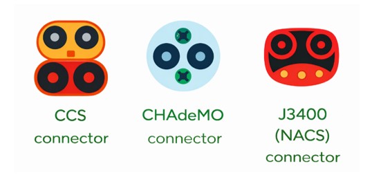
Level 2:
- Also known as Type IⅠ or AC level II
- charging through a higher-rated 240-volt AC outlet (dryer outlet) in the US and 380-400 V (three-phase) household outlet in India.
- Uses SAE J1772 connector or J3400 (NACS)
- Assumes 7 – 19 kW charging power
Onboard Charging: Both Level I and Level II chargers are Onboard chargers. Onboard charger rectifies AC to regulated DC (using active PFC, resonant converters, and DC–DC isolation), efficiency typically 93–95% at 3–19 kW range, leveraging air or liquid-cooled thermal control depending on vehicle design.
Level 3:
- Also known as DC Fast Charging
- Uses external or offboard conversion- rectification and voltage control move offboard, allowing higher power and efficiency.
- Uses Silicon Carbide (SiC) or Gallium Nitride (GaN) power devices to reduce switching losses at high frequency (>20 kHz).
- Common bus voltage: 400–800V DC, with some next-gen systems (Lucid Air, Porsche Taycan) using 900–1000V architectures.
- Liquid-cooled cables are standard above 350A of current.

Extreme Fast Charging (XFC)
Extreme Fast Charging (XFC) refers to ultra-high-power DC charging that can deliver 200–500+ miles of range in ~10–15 minutes, approaching the refueling time of conventional gasoline vehicles. It typically operates at power levels of 350 kW to 1 MW, far exceeding conventional Level 2 (AC) and standard DC fast charging systems.
Key Features
- High-Power DC Delivery: 800–1000 V architectures reduce current at the same power, minimizing cable losses.
- Advanced Power Electronics: SiC (Silicon Carbide) devices enable higher efficiency and switching frequency.
- Thermal Management: Liquid-cooled cables and battery cooling systems are essential.
- High-C-Rate Batteries: Cells designed for rapid lithium-ion transport to prevent degradation.
- Grid Integration: Often paired with on-site storage and smart energy management to reduce grid stress.
Technical Challenges
- Battery degradation due to lithium plating at high C-rates
- Grid infrastructure upgrades for MW-scale charging
- Cable heating and connector limitations
- Demand charges and utility coordination
Benefits
- Enable long-distance EV travel comparable to ICE refueling.
- Reduces range anxiety
- Critical for heavy-duty EVs (trucks, buses)
While XFC is a key enabler for widespread EV adoption, especially for highway corridors and commercial fleets, it requires coordinated advances in battery chemistry, power electronics, and grid infrastructure.
Power Electronics Backbone
Onboard Chargers (OBCs)
- Architecture: A two‑stage design — a Power Factor Correction (PFC) front end followed by an LLC resonant DC‑DC converter.
– PFC Stage: Uses boost topology to maintain near‑unity power factor (PF ≈ 0.99), minimizing reactive current drawn from the grid.
– LLC DC‑DC Stage: Converts rectified DC to a stable output voltage/current range matched to the battery.
- Switching Devices: Transition from silicon IGBTs to Silicon Carbide (SiC) MOSFETs increases switching efficiency, reduces conduction losses, and allows higher-frequency operation (up to > 100 kHz).
- Efficiency: Current commercial OBCs achieve 93–95 %, with next‑gen SiC designs targeting > 96 %.
- Form factor: Single‑phase units (3–7 kW) for home use; integrated 3‑phase OBCs (11–22 kW) in premium EVs.
- Challenges:
– Thermal losses in confined spaces (vehicle underhood).
– EMC filter design to meet CISPR 25 limits.
– Maintaining soft‑switching across variable loads.
DC Fast Charger (DCFC) Modules
- Conversion Topology:
– Three‑phase AC input → PFC rectifier → DC bus (700–1000 V).
– Multiple interleaved buck or phase‑shifted full‑bridge modules feed the EV.
– Parallel power modules scale total output (50 kW → 600 kW).
- Switching Devices: All‑SiC or GaN transistors drastically reduce heat and magnetic‑component size.
- Efficiency: Typically > 97 % at rated output; some R&D prototypes > 98 %.
- Isolation: High‑frequency transformers provide a galvanic barrier using planar magnetics for thinner form factors.
- Control: DSP or FPGA controllers run phase‑shifting PWM loops at up to 20–50 kHz, synchronizing parallel modules to avoid current imbalance.
Thermal and Cooling Strategy
Managing the heat generated by power semiconductors is critical for efficiency and durability.
Control and Sensing
- DSP/MCU executes digital current/voltage loops with PWM ≈ 20 kHz, performing soft‑start/stop sequencing.
- Real‑time telemetry: captures IGBT/MOSFET junction temperatures, bus voltage, and fault codes.
- Predictive diagnostics via edge algorithms flag ageing of capacitors or coolant pumps before failure.
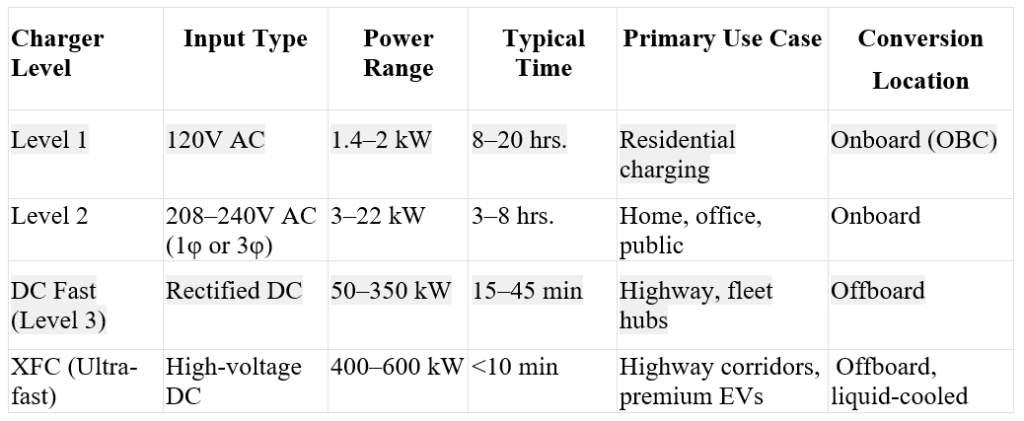
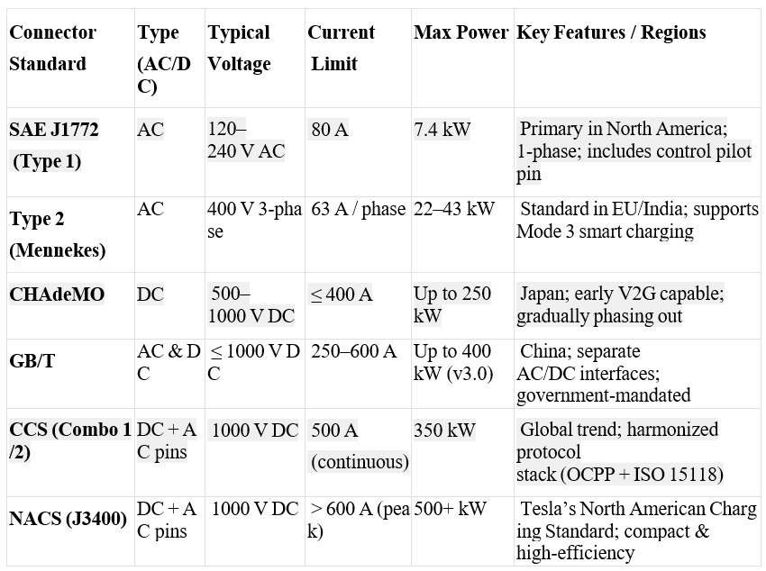
Connectors and Standards
Standardization of connectors bridges the world of automakers, consumers, and infrastructure. Each connector standard optimizes different voltages, currents, and communication frameworks.
Global Adoption by Region:
Asia-Pacific (China, Japan, Korea)
- China’s public DC fast-charging network exceeds 1 million units, with ultra-fast chargers in every major metro.
- Japan is focusing on next-gen CHAdeMO 3.0 with 400 kW and bidirectional capabilities.
- Growing research on battery swapping and smart energy management (NIO, Gogoro, etc.).
Europe
- Emphasis on interoperability and open data infrastructure across the EU.
- Networks like IONITY and Fastned prioritize multi-standard ultra-fast charging at 150–350 kW.
- Increasing integration of renewable energy microgrids at highway rest areas.
North America
- Tesla’s NACS standard is becoming mainstream, with Ford, GM, and Rivian signing on.
- Deployments under NEVI target 50-mile spacing on highways using CCS/NACS hybrid support.
- Growth in fleet and depot charging for logistics electrification.
Emerging Markets
- India: 12,000+ public chargers (2024), adding 600–800 new stations monthly.
- Africa and Latin America: Solar microgrids serve remote or off-grid EV users, especially for two- and three-wheelers.
Most modern EVs now support either CCS or NACS, both of which are evolving toward universal compatibility.
Next Gen EV Charging Hardware Innovations
The next decade of charger hardware development will merge mechanical innovation + AI control + renewable integration.
Inductive & Dynamic Charging
- Static pads: 11–50 kW systems embedded in garage floors or bus depots.
- Dynamic lanes: Copper coils buried under the road surface charge vehicles on the move (used in Sweden & Israel).
- Resonant frequency control optimizes coupling efficiency (≈ 90 %) under misalignment.
- Benefits: no physical wear / no exposed conductors / weather‑proof.
Modular Rack‑Based Chargers
- Each module (≈ 15 kW) operates autonomously; the system controller balances load across modules.
- Enables scalable installations: 45‑ → 350 kW simply by stacking modules.
- Mean‑time‑to‑repair < 15 min — hot‑swap modules reduce downtime.
AI‑Augmented Thermal Algorithms
- Predictive neural models link ambient temp, load profile & coolant flow to maintain semiconductor junction < 140 °C.
- Self‑learning controllers optimize fan/pump speed versus acoustic noise.
- Fleets use cloud analytics to correlate charger health with energy demand patterns.
Integration with Renewables and Storage
- Incorporating bi‑directional inverters so chargers double as grid‑forming devices.
- Co‑located battery energy storage systems (BESS) provide peak‑shaving and backup.
- Hybrid PV+EVSE hubs reduce grid dependency by 20–30 %.
In Summary
EV charging hardware is now a field of advanced power electronics and safety engineering. Future developments point toward smarter, lighter, and faster charging systems that use high-frequency converters, AI-based cooling optimization, and modular components. Each of these subsystems — power modules, connectors, high‑voltage loops, and future innovations — together define the trifecta of efficiency ↑, speed ↑, and sustainability ↑ that will drive the next decade of e‑mobility hardware evolution.
Next, we’ll move from hardware to brain — exploring the protocols, intelligence, and communication systems that make chargers smart and connected.
About the author

Alekhya Vaddiraj is a clean energy strategist and engineering leader with over a decade of experience driving grid modernization, distributed energy integration, and infrastructure resilience initiatives. She has worked in multidisciplinary teams and multi-stakeholder collaborations across utilities, research institutions, and industry consortia, contributing to DOE- and CEC-funded programs in EV infrastructure, demand response, and energy cybersecurity.
Currently pursuing a PhD in Electrical Engineering, Alekhya combines deep technical expertise in Power Systems with strategic program execution — translating complex engineering challenges into scalable, policy-aligned solutions that accelerate the transition to reliable, low-carbon energy systems.
This article was also published in EVreporter Mar 2026 magazine.
Also read: Building EV charging infrastructure for commercial and Industrial Vehicles
Subscribe & Stay Informed
Subscribe today for free and stay on top of latest developments in EV domain.